


What Can a Multimeter Do?
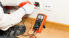
You will see multimeters that are both digital and analog with each type providing similar data that can be used when troubleshooting electrical issues. When a multimeter is used in the voltmeter mode, it is capable of measuring the amount of voltage that is moving through a given circuit. The voltage reading displayed when using in the voltmeter mode will give a reference voltage to compare against the expected or normal reading for a given circuit. In absence of past, historical data, this reading can be compared to the expected voltage reading for the circuit provided in the equipment’s operating manual.
When a multimeter is used as an ammeter, it will measure the amount of current that passes across the circuit being tested. In order to use the device in this manner, the multimeter has to be connected in series with the circuit in order to measure the amperage of the electricity passing through the circuit. Many, less-expensive multimeters are not able to measure amperage depending on the model that is being used.
Using a multimeter as an ohmmeter entails projecting the amount of resistance expected across a circuit, then disconnecting the equipment being powered in order to allow the unit to measure the inherent system resistance from the power output from the multimeter.

Multimeter Capability Options
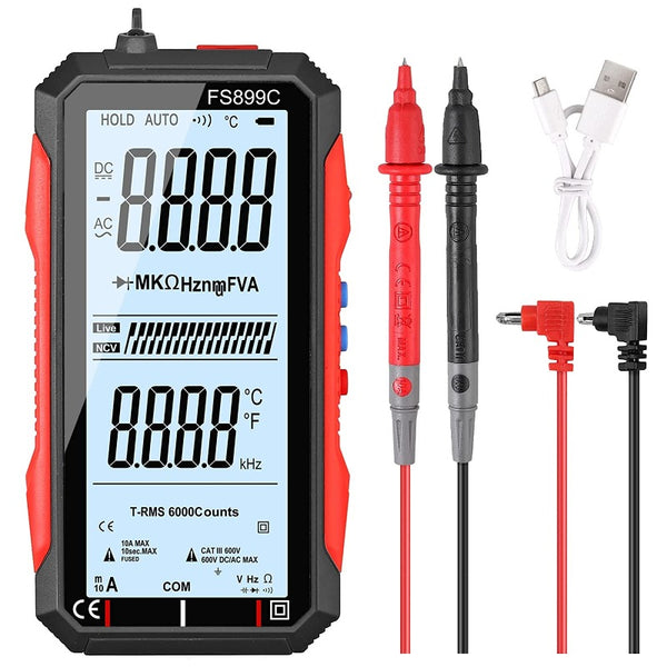
When choosing a multimeter there are a number of options to select from. Some of the core capabilities to check when acquiring a new multimeter include continuity testing, resistance testing ranges from 10 Ohms to 1 Mega Ohm, an AC voltage test to 1 V and up to 200 Volts, diode testing, and DC testing to 100mv to 50 V. Other features that consumers look for in multimeters include an auto turn-off feature, auto-ranging for the testing ranges, and an easy to charge or replace battery.
How to Use a Multimeter to Measure Resistance?
Step 1
To use a multimeter to measure the resistance of a circuit, the first thing that you need to do is set the meter to the “Resistance” or “Ohms” mode.
Step 2
Connect the black or negative lead of the device to the ground lead of the meter which can also be labeled “negative” or “-.”
Step 3
Connect the positive or red lead of the multimeter to the positive side of the meter or if labeled, the part of the device annotated with the “Ohm” symbol.
Step 4
Set the range of the multimeter to that you are intending to measure. Most of the time this will be the “R x 100” range.
Step 5
Test for a “0 Ohm Reading” by holding the two test leads together. If the measurement is no 0, then consider replacing the meter’s batteries before proceeding with testing.
Step 6
Measure the resistance across the circuit you are troubleshooting by placing the black probe towards the ground end of the circuit and the red probe one the opposite side of the suspected bad circuit or gear and annotate the output.
Setting UP the Voltmeter to Test for Voltage
Step 1
Choose the meter setting for testing for the highest range of voltage permitted. When set too low on an initial test, the voltmeter can become damaged if the voltage in a circuit exceeds the limits placed on the voltmeter.
Step 2
Insert the ground lead in the negative or “-” position.
Step 3
Insert the red lead in the “Voltage” or positive terminal.
Step 4
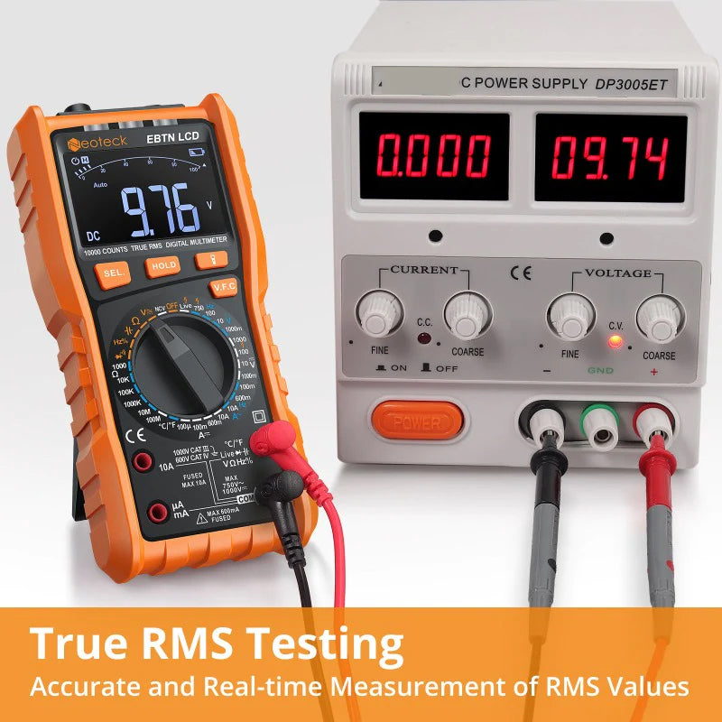
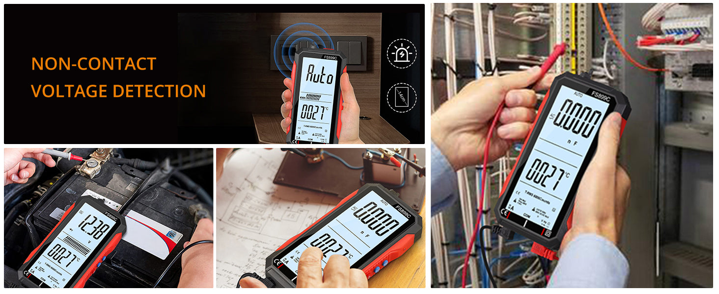
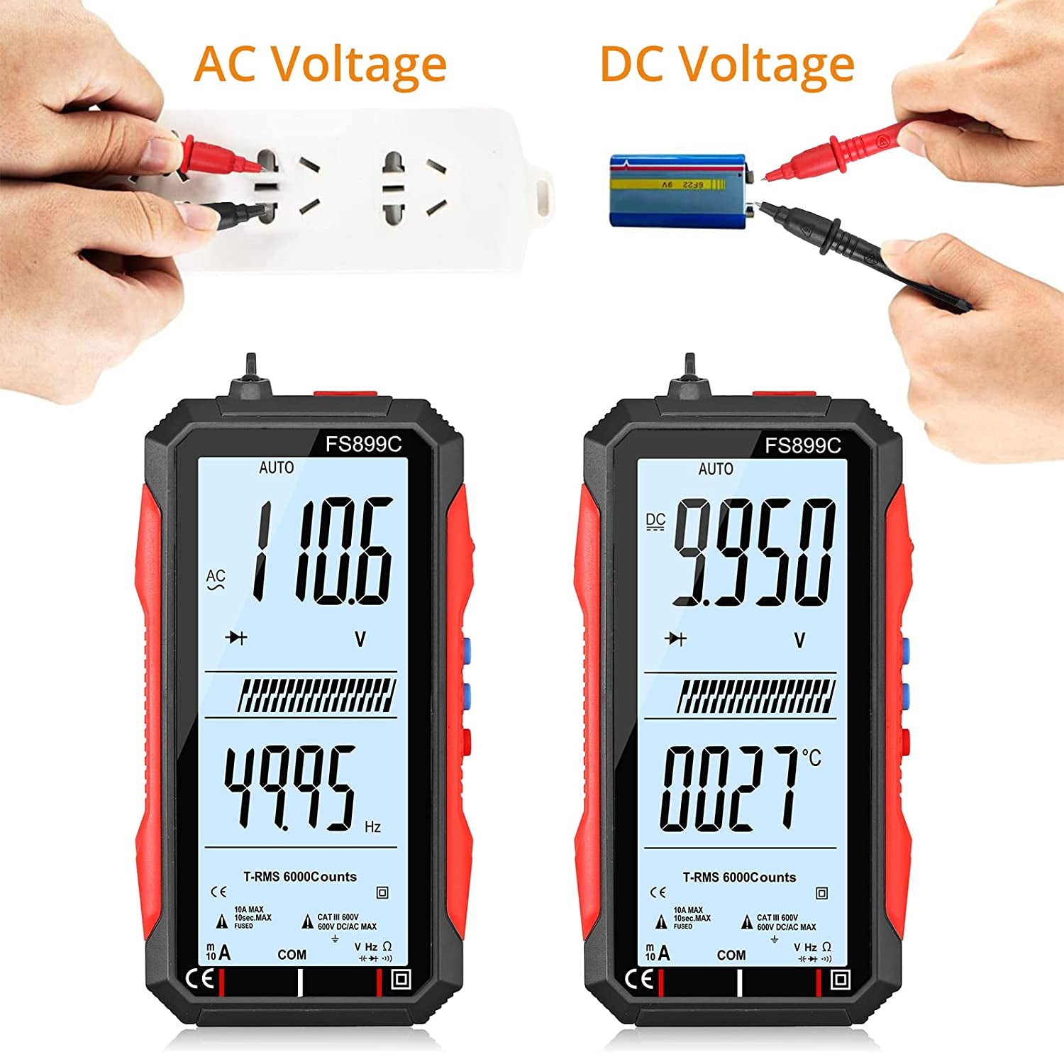
Test a known voltage output such as a wall socket that in the United States should read between 120 and 240 volts. Note, that many voltmeters will also require you to select the type of current (AC or DC) as well and can give a false reading of 0 voltage if the incorrect current type is selected on the meter.
Setting up the Voltmeter to Test for Current
Step 1
Choose the appropriate amperage type to test for on the multimeter, AC or DC
Step 2
Choose the highest most range on the meter for testing. The majority of multimeters test in extremely small measures of current so ensure you are using a meter rated for the equipment that you are going to test to avoid damage to the meter.
Step 3
Insert the ground probe into the negative or “-” terminal on the meter.
Step 4
Insert the positive or red probe into the amperage or “A” terminal on the meter.
Step 5
Turn off the power to the circuit you are testing
Step 6
Insert the meter in series with the circuit following the polarity (positive lead to the positive end of the circuit) and apply power to the circuit.


